Think of a circuit board as the brain of your garage door opener. It’s the part that processes signals from your remote and tells the opener what to do. If this “brain” is having issues, your garage door might not respond at all or could behave erratically. So, how do you test this critical component? Let’s break it down step by step, as if you and I are diving into this project together over a coffee.
Understanding the Basics of Your Sears Circuit Board
Before diving into the testing process, it helps to know what a circuit board looks like and how it functions. The circuit board on your Sears garage door opener is a small green or gray panel with lots of tiny components soldered onto it. These include chips, resistors, and capacitors—all working together to control operations.
What you might not realize is that the circuit board processes signals from the remote control and executes the right command. When you press the button on your remote, it sends a signal to the opener’s circuit board, telling it to open or close the door. So, when you notice your door isn’t moving as it should, the issue might lie here, and understanding how to test it can save you a lot of headaches.
Gathering Your Tools
First things first, let’s gather the tools you’ll need for this project. Trust me, having everything lined up from the start will save you time. Here’s a handy list:
- Multimeter: This device will help measure the electrical signals on the circuit board.
- Screwdriver: For opening up the garage door opener’s casing.
- Safety gloves: Protect your hands from any sharp edges.
- Flashlight: You might need extra light to see the components clearly.
- Sandpaper or a small file: This can be handy if you need to clean up any corrosion.
With your tools in hand, you’re already one step closer to diagnosing the problem! Honestly, having the right equipment can make a world of difference as you work on this.
Disassembling the Opener
Now that you have your tools, it’s time to take a look inside the garage door opener. Here’s how to do that safely and effectively:
1. Power Off: Start by unplugging the opener to ensure your safety. You wouldn’t want any surprises while working with electrical components.
2. Remove the Cover: Use your screwdriver to take off the casing. Most times, you’ll find a few screws holding it in place. Keep these in a safe spot so they don’t get lost!
3. Locate the Circuit Board: Once the cover is off, you’ll see the circuit board usually attached to the main assembly. It’s often one of the most prominent components inside.
While you’re doing this, don’t rush; take your time to familiarize yourself with how everything fits together. This knowledge will come in handy when you put it all back together later!
Examining the Circuit Board
Your next step is to visually inspect the circuit board for any apparent damage. Here’s what to look for:
– Burnt Spots: You’re checking for any discoloration or burnt areas, which indicate overheating.
– Loose Connections: Wiggle the plug-in connections to see if any feel loose. If they do, this could be where the problem lies.
– Corrosion: Look for any rust-like spots, which could affect connectivity. If you notice corrosion, you may be able to clean it off carefully with sandpaper.
This part might feel a bit like a detective hunt. The more you observe, the better your chances of picking up on what’s gone wrong. You might be thinking, “But what if I don’t see anything?” Don’t worry—there’s still more to do!
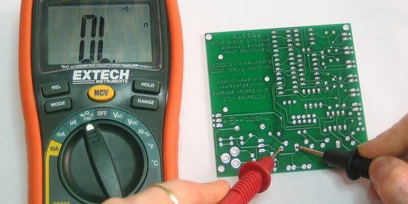
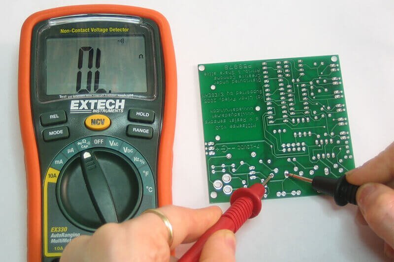
Testing with a Multimeter
Testing the circuit board with a multimeter is where things get a bit technical but still very manageable. Here’s how to go about it:
1. Set the Multimeter: Turn your multimeter dial to the “voltage” setting. You want to measure DC voltages, usually around 20V.
2. Check the Power Supply: Locate the power input on the circuit board. Put the multimeter probes to the corresponding terminals. You should get a reading that matches the voltage indicated on your circuit board’s specifications. If you don’t, there’s a power supply issue.
3. Test the Connections: Next, check the connections leading to other components. For instance, try measuring continuity on the wires connected to the motor. A reading of zero indicates a break or faulty connection.
Engaging with the multimeter can be a bit daunting, but think of it like listening for a friend’s heartbeat—you’re checking for life in the system.
Interpreting the Results
After you’ve run your multimeter tests, it’s time to interpret what you’ve found. If you’ve discovered faulty readings or signs of damage, this often means the circuit board is indeed the problem. If everything seems in order but your garage door still isn’t reacting, the issue might lie elsewhere, potentially in the remote, the motor, or wiring connections.
But don’t lose hope! Many good repair shops can offer you insights on what’s next. And if you decide to replace the circuit board yourself, just make sure to follow the model specifications.
Reassembling Your Garage Door Opener
Whether you’ve tested and fixed the board or decided to replace it, it’s now time to put everything back together. Here’s how:
1. Reconnect the Components: Securely reconnect any loose wires or connections.
2. Replace the Cover: Carefully put the casing back on, ensuring all screws are tightened.
3. Power Up: Plug in your garage door opener and test it out with your remote to see if everything works.
This step can be a bit of a nail-biter—after all, it’s the moment of truth! But remember, you did the legwork, and whatever the outcome, you’re learning valuable skills along the way.
Why Testing the Circuit Board Matters
Testing your Sears circuit board is more than just a simple task; it’s essential for the longevity of your garage door opener. Regular checks can help prevent future breakdowns. By understanding how to troubleshoot, you’re empowered to address problems early, reducing the likelihood of being stuck with a non-functional door.
Think of it as routine maintenance—like changing the oil in your car. It’s a small investment of time to save you from bigger headaches later on. If you find yourself frequently needing to test or fix the circuit board, it might also be a sign to explore newer models or alternatives.
Remember, you’re not just a passive user of your garage door opener; you’re taking charge of its functionality. This hands-on experience can build not just your confidence in DIY projects but also give you the satisfaction of solving problems yourself.
In conclusion, testing your Sears circuit board isn’t just achievable, it’s a pathway to understanding how your garage door works. With a mix of tools, patience, and observation, you can determine whether your circuit board is the source of the problem or if other issues are at play. So next time your garage door doesn’t budge, you’ve got the knowledge to tackle the problem head-on!