You might be wondering how to dive into this. Testing a Raynor circuit board sounds complicated, but don’t sweat it—I’m here to walk you through it step-by-step. Whether you’re dealing with an old model or a newer one, this guide will help you clarify the process and save you time and possibly money.
Understanding the Raynor Circuit Board
Before we get into testing, it’s crucial to know what a circuit board does. Essentially, the Raynor circuit board is like a conductor at a symphony, ensuring that every part works together harmoniously. When you press your remote, it sends an electrical signal to the board, which then communicates with the motor to open or close the garage door.
Most circuit boards are designed to last for years, but like any tech, they can run into problems over time. Common culprits include power surges, faulty wiring, or even environmental factors like humidity. Understanding these elements can help you troubleshoot effectively if issues arise.
It’s also important to identify the specific model of your Raynor opener. Different models may have different setups. Checking the user manual or looking online for your model can provide you vital information that’ll come in handy during the testing process.
Gathering Tools for Testing
Getting ready to test your Raynor circuit board? You’ll want to gather a few essential tools first. Here’s what you’ll need:
- Multimeter: This is your superhero tool for measuring voltage, current, and resistance.
- Screwdriver: Typically, a Phillips screwdriver will help you access the circuit board.
- Safety gloves: Always a good idea when working with electrical components.
- Flashlight: A handy light helps you see inside tight spaces or dimly lit areas.
These tools will help you not only test the circuit board but also troubleshoot any issues effectively. While you can find most of these items in your local hardware store, having them on hand can speed up your process, allowing you to focus on successfully diagnosing your garage door troubles.
Step-by-Step Instructions for Testing
Now, let’s get into the nitty-gritty of actually testing the circuit board. Here’s a step-by-step process to guide you:
1. Power Off and Disconnect
Safety first! Before you start any testing, unplug the garage door opener from the wall outlet. It’s a simple step but crucial. You wouldn’t want to accidentally zap yourself while handling the circuit board.
2. Open the Cover
Using your screwdriver, remove the screws securing the cover of the opener. Once the cover is off, you’ll see the circuit board nestled inside. Take a moment to visually inspect it for any obvious signs of damage, like burnt spots or frayed wires.
3. Set Up the Multimeter
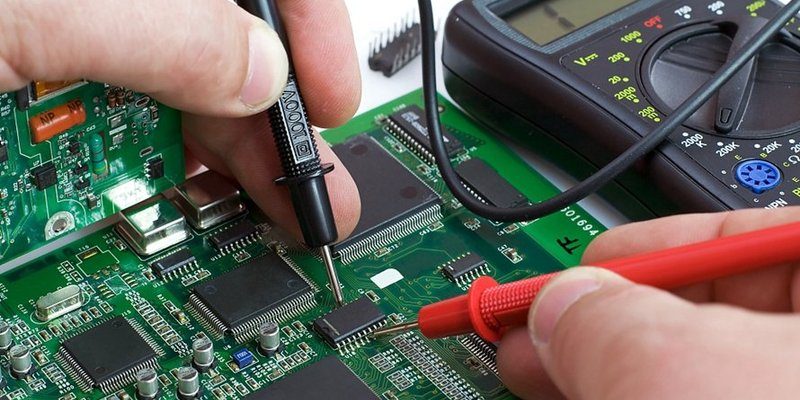
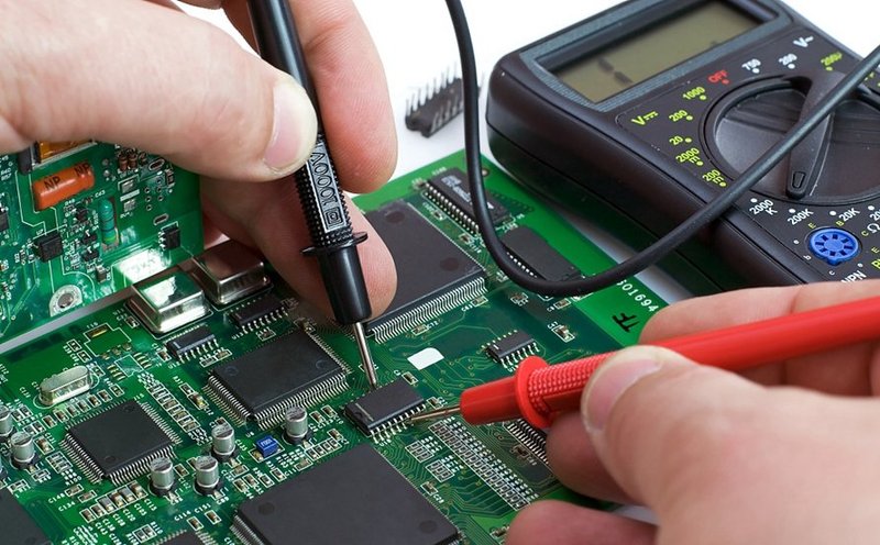
Grab your multimeter and set it to the voltage test mode. You’ll be measuring the voltage coming from the circuit board to the motor. This is a crucial step because if there’s no power getting through, that’s a big red flag.
4. Measure Voltage
Connect the multimeter probes to the designated terminals on the circuit board. Here’s a quick tip: the red probe usually goes to the positive terminal and the black probe connects to the negative. Monitor the readout on your multimeter; you should get a reading that matches your opener’s specified voltage—typically around 24V for most models. If you’re seeing zero or an unusually low number, that indicates a problem with the circuit board.
Common Issues and What They Mean
After testing, you might find you’re facing one of several common issues. Recognizing these can help you decide your next steps.
- No Voltage: If your multimeter shows zero voltage, the circuit board could be defective or there may be a bad connection.
- Low Voltage: A low reading could mean your power source is inadequate, like when a battery is dying.
- Fluctuating Readings: Inconsistent results might indicate loose wiring or other faults in the board.
No matter what you discover, take a deep breath. Diagnosing the problem is half the battle won.
When To Replace the Circuit Board
So, you’ve tested and found something off with the circuit board. The next question usually is: should you replace it? Here are some pointers to help you decide:
– If the board has visible burn marks or severe corrosion, it’s often best to replace it.
– Frequent malfunctions or consistent voltage issues likely indicate it’s time for a new board.
– Consider age; older boards may not be worth the repair costs, especially if they’re no longer under warranty.
Replacing the board might sound daunting, but it can be straightforward once you know the steps for disassembly and reassembly. It’s often just a matter of disconnecting the wires, swapping out the board, and hooking everything back up.
Final Thoughts
Testing a Raynor circuit board can seem complex, but breaking it down into simple, actionable steps makes it manageable. By arming yourself with the right tools and knowledge, you can diagnose problems and decide if repair or replacement is the best route.
You’ve now got the information to tackle this problem head-on, and hopefully, you’ll have your garage door back up and running smoothly in no time. If troubles persist, don’t hesitate to seek help from a professional. Sometimes, knowing when to call for support is just as important as knowing how to troubleshoot!