Think of a linear circuit board as the heart of a system, pumping the vital currents where they need to go. Just like with any heart, if something goes wrong, the whole system can start to falter. Testing your circuit board is like getting a check-up; it helps you spot potential issues before they become big problems. Some common examples of devices that use linear circuit boards include audio amplifiers, power supplies, and radios. With the right techniques, you can ensure your devices sing instead of sputter.
In this guide, I’ll walk you through the straightforward steps and tools you need to test a linear circuit board, revealing how it all works in a way that makes sense—even if you’re new to electronics. Ready to dig in? Let’s get started!
Essential Tools for Testing
Before you start testing a linear circuit board, having the right tools can make a world of difference. Imagine trying to cook without proper utensils; it just wouldn’t work. In the electronics world, your toolkit will likely include the following:
- Multimeter: This handy device is a must-have. It measures voltage, current, and resistance, letting you check if your components are alive and kicking.
- Oscilloscope: Picture this as a video camera for electrical waves. It lets you visualize the changes in voltage over time, helping to diagnose complex issues.
- Soldering Iron: Sometimes, you’ll need to fix or replace parts. A good soldering iron will help you make precise repairs when things go wrong.
- Test Probes: These are your hands in the circuit. They let you tap into different points to gather measurements while you test.
Having these tools ready ensures you’re well-prepared to tackle any testing task that comes your way.
Understanding the Circuit Board Layout
Let’s break down the linear circuit board itself. At first glance, it may seem a bit daunting, but understanding its layout is key to effective testing. A typical linear circuit board features active components like transistors and operational amplifiers, as well as passive components such as resistors and capacitors.
Here’s the thing: each component plays a crucial role. For instance, resistors regulate the flow of electrons, and capacitors store energy. If one little part goes awry, it impacts the whole board. Familiarizing yourself with the layout helps you know where to direct your testing efforts.
To visualize this, think of a city map. Each street and landmark has a purpose. Knowing where everything is located helps you navigate quickly to the areas that might need inspection.
Performing a Visual Inspection
Before diving into technical measurements, a simple visual inspection can reveal a lot about your linear circuit board. It’s like taking a quick glance under the hood of a car—sometimes, you can spot the issue before even turning the engine on.
Here’s what to look for during your inspection:
- Burn Marks: Look for any scorch marks or discoloration. These can indicate overheating, which is a sign of bigger problems.
- Loose Connections: Inspect all solder joints and connections. If something appears wobbly, there’s a chance it’s causing intermittent problems.
- Component Damage: Check for cracked or broken components. Even small damage can disrupt function.
Taking the time to do a thorough visual inspection can save you from unnecessary hassle later on.
Using a Multimeter for Testing
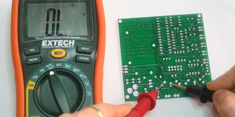
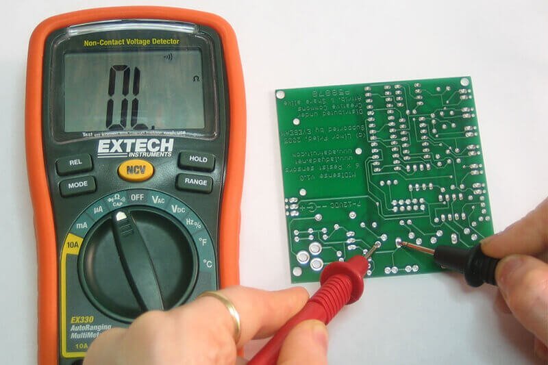
Once you’ve done a visual check, it’s time to wield the multimeter. This little gadget will become your best friend during testing. Here’s how to use it:
1. Set Up Your Multimeter: Start by selecting the correct setting—whether you’re measuring voltage (V), current (A), or resistance (Ω).
2. Testing Voltage: Place the probes on the points of interest. For example, if you’re checking the output voltage of an amplifier, make sure the system is powered on. A healthy voltage reading means that part is working as it should.
3. Measuring Resistance: Power off the circuit before measuring resistance. You’ll want to check resistors by placing the probes on either side. A reading close to the resistor’s value confirms it’s functioning properly.
4. Checking Current: When measuring current, use a series connection to avoid damaging your multimeter—this isn’t a task for the faint of heart!
Letting the multimeter guide you through these steps will help pinpoint issues quickly and effectively.
Testing with an Oscilloscope
The oscilloscope may sound intimidating at first, but once you get comfortable, it’s a powerful tool that provides a view of what’s happening inside your circuit. It’s like having X-ray vision for electrical signals. Here’s how you can use it:
1. Connect the Probes: Attach your oscilloscope probes to the circuit points you want to test. Make sure to follow the polarity—connecting them incorrectly can lead to inaccurate results.
2. Analyze the Waveform: As you power the circuit, observe the waveform on the screen. It should look clean and stable. If you see irregular spikes or flat lines, that indicates potential issues.
3. Comparing Signals: You might use the oscilloscope to compare signals at various points in the circuit. This comparison can help you identify where the signal might be dropping or distorting.
Using an oscilloscope takes practice, but it’s well worth the effort for more in-depth testing.
Troubleshooting Common Issues
Testing a linear circuit board often leads to a few common issues. Don’t worry; they’re usually fixable! Here are some potential problems you might encounter:
- Power Issues: If the circuit isn’t powering up, check the power source first. Ensure everything is connected correctly and that there’s voltage coming in.
- Distorted Signals: If you see a distorted waveform on your oscilloscope, it could mean components like capacitors or op-amps are malfunctioning.
- Overheating: If parts are getting hot to the touch, it could be due to overcurrent or bad connections. This is a red flag and needs addressing immediately.
Identifying these common problems helps streamline your testing process, saving you time and frustration.
When to Seek Professional Help
At times, you might find yourself in over your head. Maybe you’ve tested everything and still can’t pinpoint the issue. Here’s the deal: seeking professional help isn’t a sign of failure; it’s a smart move.
Consider reaching out when you face:
- Complex Repairs: If the issue involves multiple components or complex soldering, professionals have the experience to tackle these problems efficiently.
- Time Constraints: If you don’t have the time or tools to conduct thorough testing, getting someone with expertise can save you both time and stress.
- Safety Concerns: If there’s anything that could be dangerous—like dealing with high voltages—don’t hesitate to call a pro. Your safety is paramount.
Remember, even the most experienced electronics enthusiasts sometimes require a helping hand.
In conclusion, knowing how to test a linear circuit board equips you with valuable skills for working with electronics. From your trusty multimeter to understanding your circuit’s layout, each step becomes easier with practice. So, the next time you find yourself troubleshooting or tuning up a board, you’ll be ready to tackle the challenge head-on. Happy testing!